Improve your search results. Select your educational institution and subject so that we can show you the most relevant documents and help you in the best way possible.
Ok, I understand!
Your school or university
Improve your search results. Select your educational institution and subject so that we can show you the most relevant documents and help you in the best way possible.
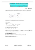
Draw a logic circuit that performs the following Boolean expression: Y=A∙((B+C)) ̅.
Determine the Boolean expression for the circuit shown below.
Write the Boolean expression for the logic circuit shown below.
Develop the truth table for the circuit shown in Problem 4.
Develop the truth table for the circuit shown below.
Develop the Boolean expression for the circuit shown in Problem 6.
Draw a logic circuit using only NAND gates to implement the following Boolean expression:...
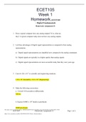
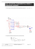
ECET 105 DIGITAL FUNDAMENTALS WEEK 4 HOMEWORK ANSWER,GRADED A.
Last document update:
ago
Draw a logic circuit that performs the following Boolean expression: Y=A∙((B+C)) ̅.
Determine the Boolean expression for the circuit shown below.
Write the Boolean expression for the logic circuit shown below.
Develop the truth table for the circuit shown in Problem 4.
Develop the truth table for the circuit shown below.
Develop the Boolean expression for the circuit shown in Problem 6.
Draw a logic circuit using only NAND gates to implement the following Boolean expression:...
What is the duty cycle for a square wave signal that is HIGH for 15 nsec and LOW for 30 nsec?
2. A pulse train is shown on the oscilloscope below. Determine the period of the pulse.
3. Determine the frequency for a pulse that occurs every 10 ms.
4. What is the base-10 value for the binary number 11012?
5. What are the respective weights of the 1s in Problem 4?
6. How many different values can be represented by 6 bits, 7 bits, 8 bits, and 10 bits?
7. What is the minimum number of bi...
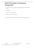
ECET105 Week 2 Homework Assignment,WELL EXPLAINED WITH VERIFIED ANSWERS.
Last document update:
ago
What is the duty cycle for a square wave signal that is HIGH for 15 nsec and LOW for 30 nsec?
2. A pulse train is shown on the oscilloscope below. Determine the period of the pulse.
3. Determine the frequency for a pulse that occurs every 10 ms.
4. What is the base-10 value for the binary number 11012?
5. What are the respective weights of the 1s in Problem 4?
6. How many different values can be represented by 6 bits, 7 bits, 8 bits, and 10 bits?
7. What is the minimum number of bi...
Does a typical computer have any analog outputs? If so, what are they?
List three advantages of digital signal representation as compared to their analog representation.
Convert 126 x 10+2 to scientific and engineering notations.
Make the following conversions:
a. Convert 0.34 seconds to milliseconds.
b. Express 0.0005 x 10⁻⁴ farads as picofarads.
The frequency of a signal is equal to the reciprocal of the signal’s period (f = 1/p).
The signal shown below is a sine wave as it might be d...
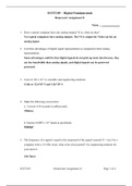
ECET 105 DIGITAL FUNDAMENTALS WEEK 1 HOMEWORK ANSWER
Last document update:
ago
Does a typical computer have any analog outputs? If so, what are they?
List three advantages of digital signal representation as compared to their analog representation.
Convert 126 x 10+2 to scientific and engineering notations.
Make the following conversions:
a. Convert 0.34 seconds to milliseconds.
b. Express 0.0005 x 10⁻⁴ farads as picofarads.
The frequency of a signal is equal to the reciprocal of the signal’s period (f = 1/p).
The signal shown below is a sine wave as it might be d...
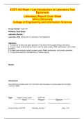
ECET-105 Week 1 Lab Introduction to Laboratory Test Equipment (VERSION 2) With Latest Solutions Grade A
Study guide • 6
pages
• 2020
ECET-105 Week 2 Lab: Soldering Techniques and the Electronic Die Kit
Objectives:
To learn the basics of soldering.
….. produce mechanically and electrically sound solder joints.
To assemble the Electronic Dice Kit.
Results: ► Conclusions: ► Observations/Measurements: Describe any problems you had with assembling the analog meter kit. ► Questions: ▼
What is the purpose of core in hollow solder wire?
What is tinning and why is it important?
Why is safety so important when soldering?
Wh...
ECET-105 Week 1 Lab Introduction to Laboratory Test Equipment (VERSION 2) With Latest Solutions Grade A
Last document update:
ago
ECET-105 Week 2 Lab: Soldering Techniques and the Electronic Die Kit
Objectives:
To learn the basics of soldering.
….. produce mechanically and electrically sound solder joints.
To assemble the Electronic Dice Kit.
Results: ► Conclusions: ► Observations/Measurements: Describe any problems you had with assembling the analog meter kit. ► Questions: ▼
What is the purpose of core in hollow solder wire?
What is tinning and why is it important?
Why is safety so important when soldering?
Wh...
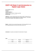
ECET-105 Week 3 Lab Introduction to Digital Logic Gates (VERSION 2) With Latest Updated Solutions
Study guide • 9
pages
• 2020
ECET-105 Week 3 Lab Introduction to Digital Logic Gates
ECET-105 Week 3 Lab: Introduction to Digital Logic Gates
Objectives:
To understand basic logic functions (AND, OR, and NOT) and their complement used in Boolean algebra and digital logic design.
To test simple logic small-scale integration (SSI) integrated circuit (IC) devices.
Results: ► Conclusions: ► Observations/Measurements: ► Questions: ▼
Draw the schematic for a circuit that will function as indicated by the Boolean expres...
ECET-105 Week 3 Lab Introduction to Digital Logic Gates (VERSION 2) With Latest Updated Solutions
Last document update:
ago
ECET-105 Week 3 Lab Introduction to Digital Logic Gates
ECET-105 Week 3 Lab: Introduction to Digital Logic Gates
Objectives:
To understand basic logic functions (AND, OR, and NOT) and their complement used in Boolean algebra and digital logic design.
To test simple logic small-scale integration (SSI) integrated circuit (IC) devices.
Results: ► Conclusions: ► Observations/Measurements: ► Questions: ▼
Draw the schematic for a circuit that will function as indicated by the Boolean expres...
ECET105 – Digital Fundamentals Homework Assignment Week 3 (VERSION 1) With Best Rated/Latest Solutions
Summary • 3
pages
• 2020
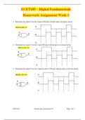
ECET 105 Week 3 Homework Assignment # 3
1. Determine the output X for the 2-input AND gate with the input waveforms shown.
1. Determine the output X for the 2-input OR gate with the input waveforms shown.
1. Determine the output X for the 2-input Exclusive-OR gate with the input waveforms shown.
2. Determine the output X for the 2-input NAND gate with the input waveforms shown.
1. Is the output from the NAND gate shown in Problem 4 active-HIGH or active-LOW? Why?
2. Download from a semiconductor...
ECET105 – Digital Fundamentals Homework Assignment Week 3 (VERSION 1) With Best Rated/Latest Solutions
Last document update:
ago
ECET 105 Week 3 Homework Assignment # 3
1. Determine the output X for the 2-input AND gate with the input waveforms shown.
1. Determine the output X for the 2-input OR gate with the input waveforms shown.
1. Determine the output X for the 2-input Exclusive-OR gate with the input waveforms shown.
2. Determine the output X for the 2-input NAND gate with the input waveforms shown.
1. Is the output from the NAND gate shown in Problem 4 active-HIGH or active-LOW? Why?
2. Download from a semiconductor...
ECET-105 Week 4 Lab Logic Circuit Design, Simplification, Simulation & Verification
Objectives: The objective of this week’s lab was to design a digital logic circuit using a truth table and sum-of-product(SOP) formulation as well. We also figured out in this week’s lab how to access and use Multisim when using Boolean expressions and the truth table also. Finally, once we figured how to how properly use Multisim, we started to build and test the logic circuit to verify that the system perfo...
ECET-105 Week 4 Lab Logic Circuit Design, Simplification, Simulation & Verification (VERSION 2) With Complete Updated;Latest Solutions
Last document update:
ago
ECET-105 Week 4 Lab Logic Circuit Design, Simplification, Simulation & Verification
Objectives: The objective of this week’s lab was to design a digital logic circuit using a truth table and sum-of-product(SOP) formulation as well. We also figured out in this week’s lab how to access and use Multisim when using Boolean expressions and the truth table also. Finally, once we figured how to how properly use Multisim, we started to build and test the logic circuit to verify that the system perfo...
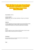
ECET 105 Week 4 Homework Assignment Week 4 Version 1 ;With Latest Updated/Verified Solution And Answers
Summary • 4
pages
• 2020
ECET 105 Week 4 Homework Assignment # 4 (2 Versions)
Draw a logic circuit that performs the following Boolean expression: .
Determine the Boolean expression for the circuit shown below.
The Boolean expression for an AND gate is . Does the expression also describe an AND gate? Prove your answer.
Write the Boolean expression for the logic circuit shown below.
Develop the truth table for the circuit shown in Problem 4.
…… the truth table for the circuit shown below.
Develop the Boolean expressi...
ECET 105 Week 4 Homework Assignment Week 4 Version 1 ;With Latest Updated/Verified Solution And Answers
Last document update:
ago
ECET 105 Week 4 Homework Assignment # 4 (2 Versions)
Draw a logic circuit that performs the following Boolean expression: .
Determine the Boolean expression for the circuit shown below.
The Boolean expression for an AND gate is . Does the expression also describe an AND gate? Prove your answer.
Write the Boolean expression for the logic circuit shown below.
Develop the truth table for the circuit shown in Problem 4.
…… the truth table for the circuit shown below.
Develop the Boolean expressi...
Make study stress less painful
Study stress? For sellers on Stuvia, these are actually golden times. KA-CHING! Earn from your study resources too and start uploading now.
Discover all about earning on Stuvia